Author: Site Editor Publish Time: 2025-08-22 Origin: Site
Last updated: September 1, 2026
Selecting a short-wave infrared lamp for paint curing starts with the coating specification and the workpiece, not with a promotional comparison or a single wattage figure. A suitable lamp must help the coated surface follow a controlled temperature profile while the substrate, finish quality and production sequence remain within their approved limits. This guide explains how to compare short-wave lamp constructions, arrange coverage and verify the result on the actual coating system.
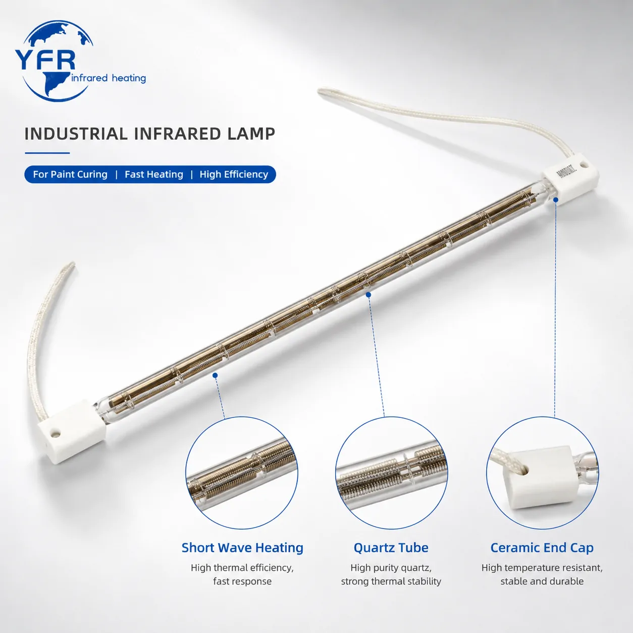
The most effective lamp is the one that produces a repeatable acceptable finish inside the required production window. It is not necessarily the lamp with the highest rated power or the brightest visible output. Establish the acceptance criteria before comparing emitters:
Coating result: adhesion, hardness, gloss, colour, texture and chemical or abrasion resistance after the specified conditioning period.
Thermal result: the required film and workpiece temperatures without hot spots, discoloration or substrate distortion.
Process result: stable performance at normal line speed, part spacing, starts, stops and recipe changes.
Integration result: safe electrical loading, suitable controls, adequate extraction and service access.
Use the coating supplier's stated flash-off and cure conditions as the starting boundary. Infrared equipment should deliver and control that process; it should not be used to invent a different cure schedule without testing.
Short-wave quartz lamps reach operating output quickly and can be divided into responsive control zones. Their radiation can be useful where a coating or underlying part absorbs the available spectrum and the process benefits from rapid, targeted heating. Reflector coatings or separate reflectors direct more of the emitted energy toward the workpiece, while the lamp-bank geometry determines how evenly that energy is distributed.
Short wave is not automatically the correct choice for every paint. A light-coloured, reflective, transparent or very thin layer may transmit or reflect part of the incident radiation. The substrate can then absorb a different proportion than the film. Pigment, film build, surface finish and angle also change the response. A controlled sample trial is therefore more reliable than selecting a lamp from coating colour or name alone.
Keep drying and curing separate in the process review. Water or solvent may need time and airflow to leave the film before a higher-temperature cure stage. Applying strong radiant heat too early can skin the surface and contribute to trapped volatiles, blistering or pinholes even when the final temperature appears correct.
Record the complete coated assembly. The same paint can require a different setting on steel, aluminium, composite or plastic because thermal mass, conductivity, reflectivity and maximum temperature differ. Complex parts also present edges, recesses and changing lamp distance that a flat test panel does not reproduce.
| Selection input | Why it matters | What to verify |
|---|---|---|
| Coating chemistry and film build | Controls flash, absorption and cure requirements | Supplier process window and actual wet or dry thickness |
| Pigment and surface appearance | Changes reflection and absorption | Test every important colour or finish family |
| Substrate material and thickness | Determines heat spreading, thermal load and distortion risk | Maximum allowable part temperature and dimensional stability |
| Part geometry and orientation | Changes distance, angle, shadowing and edge loss | Temperature distribution on production-representative parts |
| Flash-off and airflow | Supports safe release of water or solvent | Surface quality, vapour removal and exhaust requirements |
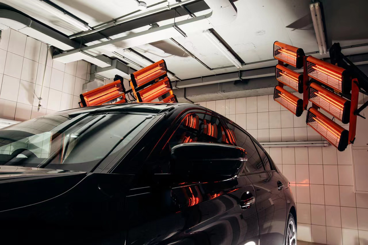
Working distance affects both intensity and uniformity. Moving a lamp closer may increase local heating but can expose filament patterns or magnify small alignment errors. Moving it farther away can broaden coverage but may reduce the useful energy reaching the surface. Compare candidate distances with a mapped temperature or irradiance pattern across the real heated area.
Choose heated lamp length, spacing and reflector geometry so adjacent patterns overlap without producing alternating hot and cold bands. Include the ends of the heated length, conveyor edges and gaps between parts. Curved or three-dimensional workpieces may need angled banks, more than one heated face or independent edge zones rather than one powerful overhead bank.
Separate flash, temperature ramp and cure or hold functions when the coating needs a staged profile. Independent zones also help compensate for edge losses and different part families. The controls should reduce output promptly during conveyor stops or empty gaps so a stationary part does not receive the normal moving-line exposure.
For a replacement lamp, match voltage, rated power, overall length, heated length, tube format, reflector position, end connections, cable length and permitted operating orientation. For a new module, also check clearances, cooling, guarding, reflector access and how failed lamps can be replaced. Wattage alone does not establish mechanical or thermal compatibility.
Responsive lamps are most useful when their output can follow a defined recipe. Provide independent zone control where the process needs separate entry, centre, edge or exit settings. Interlock lamp output with conveyor movement, extraction and enclosure conditions. The required electrical protection, guarding and ventilation must be designed for the complete machine and its operating environment.
Measure the product, not only the air around it. A pyrometer can support continuous control when its wavelength, field of view and emissivity setting suit the coated surface. Contact sensors or temperature labels can help during trials, but their response and placement must be understood. Use consistent measurement points and correlate them with finished-film tests rather than treating a single surface reading as proof of cure.
Airflow is a process variable as well as a ventilation requirement. It can remove released vapour and moderate the boundary layer, but an uneven or excessive draft can cool one area and disturb finish quality. Balance radiant power, air movement and exhaust using representative production loads.
Start with samples that represent the normal and difficult ends of production: important colours, maximum film build, highest thermal mass, thinnest heat-sensitive substrate and challenging geometry. Keep coating preparation, flash time and measurement method consistent. Change one major variable at a time so the result can be traced to lamp type, distance, zone power, airflow or exposure time.
Establish a baseline. Record the current process, defects, line speed, product temperature and accepted finish properties.
Map the heating profile. Measure the centre, edges, corners and shadowed areas throughout flash, ramp and hold stages.
Inspect after the correct interval. Evaluate appearance, adhesion, hardness and resistance only after the coating's specified cooling or conditioning period.
Find a process window. Identify upper and lower settings that still pass, then choose a production setpoint with margin for ordinary variation.
Challenge the recipe. Repeat with conveyor gaps, restarts, normal part spacing and relevant product variants before release.
A successful trial should produce documented acceptance limits, not merely one fast sample. Retain the coating batch, film thickness, lamp arrangement, working distance, zone settings, airflow and measurement results with the approved recipe.
Coating type, supplier cure schedule, colour range and wet or dry film thickness
Substrate material, part dimensions, orientation and maximum allowable temperature
Required line speed, cycle time, flash time and final quality tests
Available heated length, width, working distance and enclosure arrangement
Supply voltage, control method, airflow, extraction and stop sequence
For replacement work: lamp photographs, label data, drawings and end-connection dimensions
For a process-level overview, read the infrared paint drying and curing guide. For defect diagnosis and recipe development, see infrared paint drying process control and defect prevention. You can also review YFR short-wave infrared lamp options and infrared heating modules and controls.
No. Useful performance depends on absorption, heated length, distance, reflector design, coverage, exposure time and control. Excess local intensity can reduce the available process window.
Do not assume so. Pigment and finish can change absorption and reflection. Test the important colour families and keep separate recipes where the measured response differs.
Check lamp spacing, working distance, reflector condition, part alignment and zone balance. Map temperatures across a representative part before changing total installed power.
No. The coating's required flash stage and the machine's vapour-control provisions remain part of the process. Radiant heating, airflow and extraction must be coordinated.
A temperature reading supports process control, but final proof comes from the coating supplier's specified appearance and performance tests after the required conditioning period.
YFR can review a short-wave lamp replacement or a new paint-curing heating zone using your coating, part, line and electrical data. Send the coating cure requirements, product dimensions, available space, cycle target and existing lamp information so the proposed configuration can be assessed through a production-representative trial.


