Author: Site Editor Publish Time: 2025-09-22 Origin: Site
Last updated: August 29, 2026
Infrared can heat plastics for both thermoforming and welding, but the two processes need different temperature fields. Thermoforming usually requires a controlled area of sheet to soften uniformly through an appropriate depth. Welding requires local energy at an interface while protecting the surrounding part from distortion.
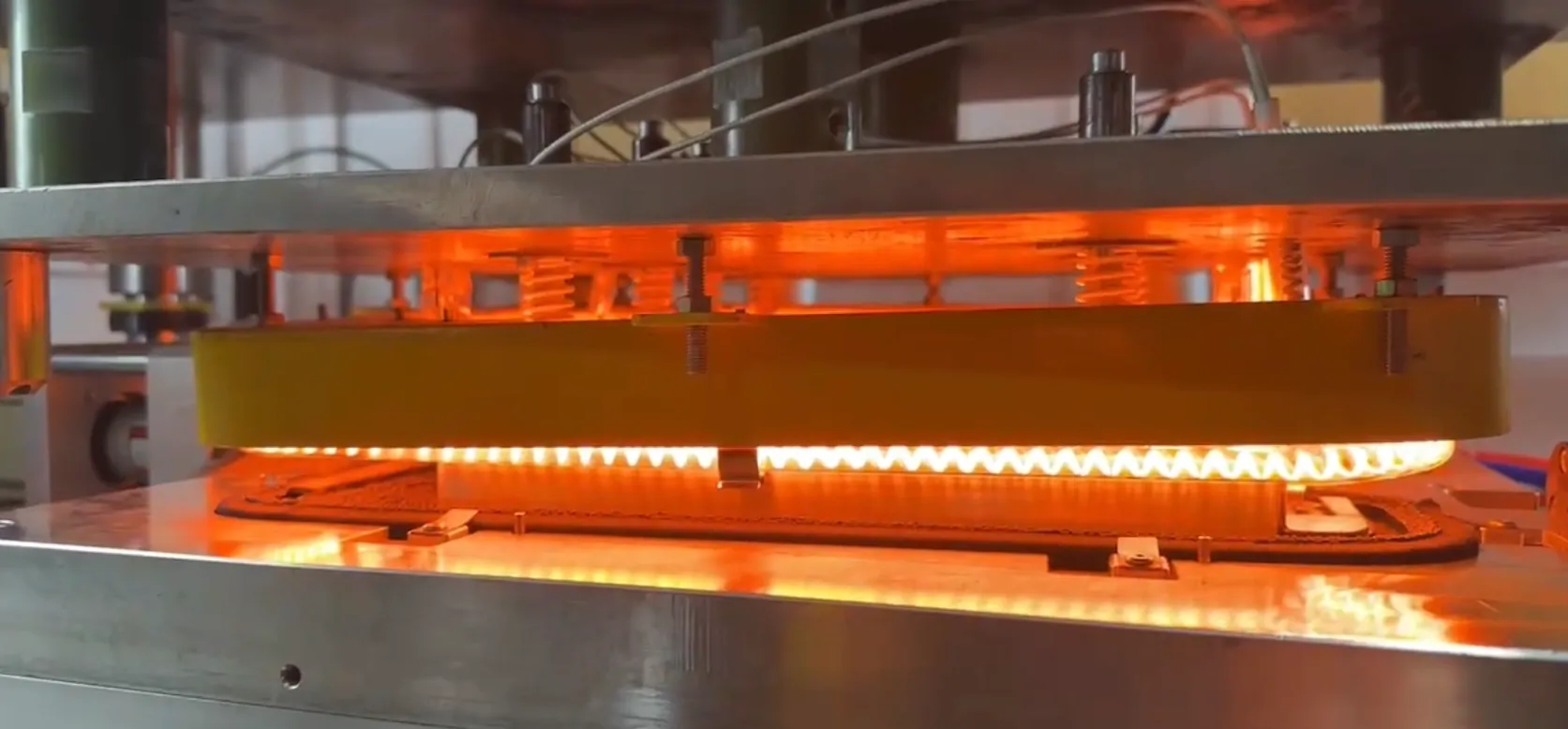
For thermoforming, identify the sheet temperature window, thickness, draw ratio and areas that stretch most. For welding, define the joint geometry, interface temperature, allowable heat-affected zone and required pressure cycle. The same lamp array should not be assumed to suit both tasks.
| Design factor | Thermoforming | Plastic welding |
|---|---|---|
| Heated area | Broad sheet or selected forming zones | Narrow joint or interface |
| Temperature objective | Uniform forming window | Local melt or activation window |
| Zoning | Compensates for edges and draw depth | Concentrates heat and protects nearby features |
| Mechanical step | Forming pressure or vacuum | Clamping and consolidation pressure |
| Quality check | Wall thickness, detail and distortion | Joint strength, seal and flash |
Polymer type, pigment, fillers, surface finish and thickness affect absorption. Transparent or reflective materials may transmit or reject part of the incident radiation. In a weld, one layer may be designed to transmit radiation while the interface absorbs it. Test the real colour and grade rather than relying on the generic polymer name.
Thermoforming arrays can use edge and centre zones to compensate for heat loss and material draw. Welding systems may use apertures, shields or reflectors to confine the heated path. Product motion can average local lamp variation, while stationary parts may require finer zoning and more careful temperature protection.
Compare YFR short-wave lamps, medium-wave lamps and infrared modules.
Surface temperature is important, but forming depends on temperature through the sheet, and welding depends on the interface. Use test coupons, section checks or embedded reference sensors where practical. For non-contact measurement, confirm emissivity, field of view and interference from reflected lamp radiation.
There is no universal choice. It depends on polymer, pigment, thickness, speed, heating depth and required response.
Edge geometry, clamp design, reflector overlap or excessive edge-zone power can create a different heat balance.
Only if the optical and interface design provides useful absorption at the joint. Material trials are essential.
Run it through the approved trial matrix because pigment changes can alter absorption, temperature response, forming behaviour and weld quality.
Send YFR the polymer, thickness, geometry and cycle data for an emitter-layout review.


