


Author: Process Heating Engineer Publish Time: 2025-10-23 Origin: Site


Last updated: August 31, 2026
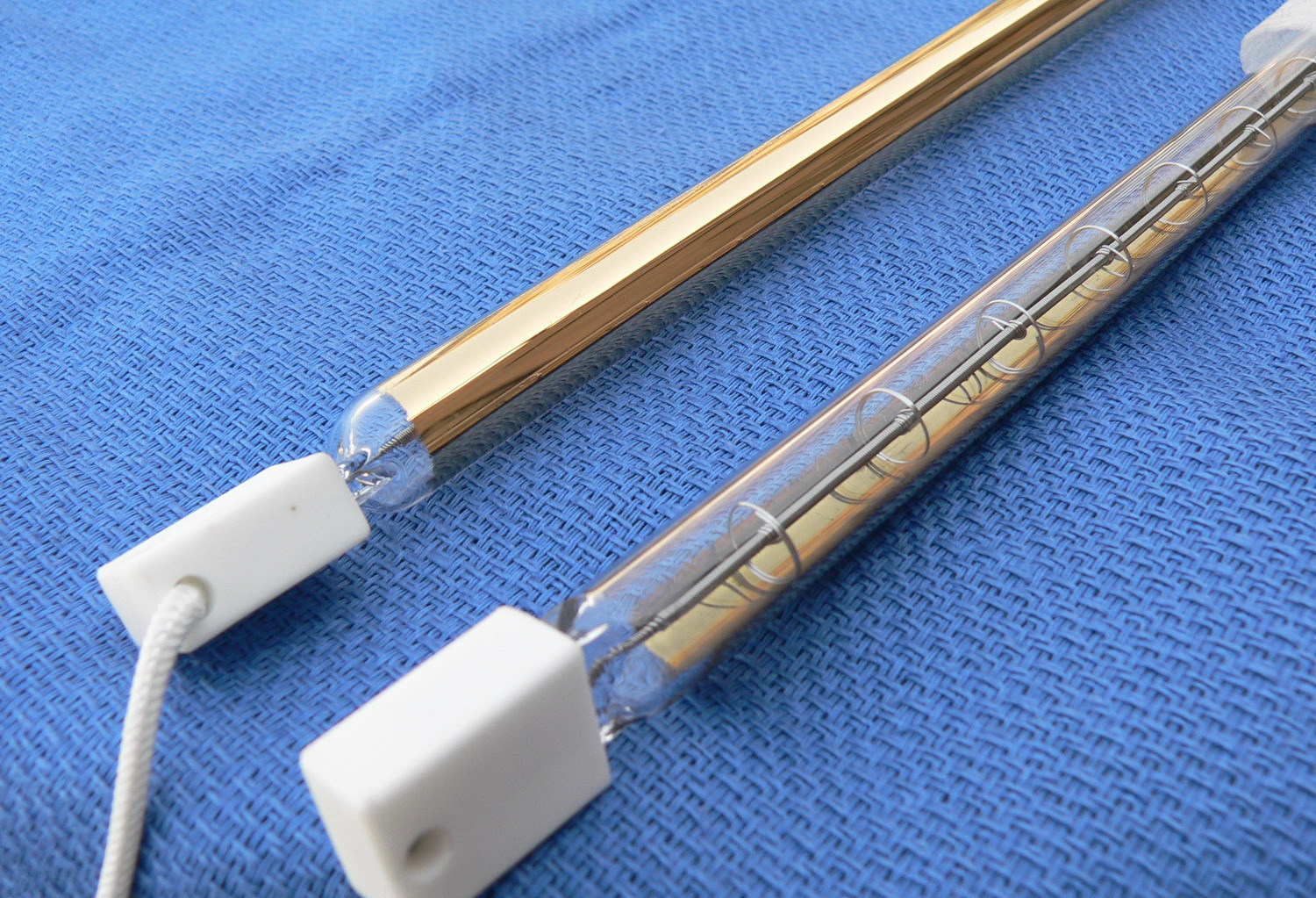
A clear quartz infrared lamp radiates in multiple directions around the tube. When a reflective coating is applied to part of the surface, radiation travelling toward the coated side is redirected toward the uncoated working side.
The coating therefore changes the direction of the radiant output. It does not create additional electrical power.
A correctly positioned gold reflector may reduce unnecessary heating behind the lamp and direct a larger portion of the radiation toward the product. The actual result still depends on coating coverage, lamp position, product width, working distance and the absorption characteristics of the material.
A gold reflector infrared lamp is normally a quartz infrared emitter with a thin reflective gold layer applied to one section of the tube.
The clear side faces the product. The coated side normally faces away from the product and redirects radiation toward the working area.
The coating can be applied to single-tube or twin-tube lamps. A gold reflector lamp may also be designed as a short wave or fast medium wave emitter.
This distinction is important. “Gold reflector” describes the direction-control structure. It does not independently define the wavelength, response speed, filament material or electrical rating.
Gold has useful reflective properties in the infrared region.
NASA explains that the mirrors of the James Webb Space Telescope use a very thin gold coating because gold improves the reflection of infrared light. The telescope application is very different from an industrial heating lamp, but it supports the underlying physical reason that gold can be used as an infrared-reflective surface.
This does not mean that an industrial gold reflector lamp transfers all input power to the product.
The lamp coating, quartz envelope, working distance, reflector condition and equipment geometry still influence the amount of radiation that reaches the target.
The NASA example supports the reflectivity of gold in the infrared region; it does not support a universal 90% system efficiency, fixed energy saving or guaranteed temperature uniformity for industrial lamps.
Without a directional coating or separate reflector, a tubular emitter sends radiation around much of its circumference.
A partial gold coating intercepts radiation travelling toward the rear of the lamp and redirects some of it through the clear working side.
A half-coated structure is common, but it is not the only possible design. Coverage may differ according to the lamp geometry, reflector angle and required heating area.
The reflective layer does not act independently. Quartz transmission, coating quality, lamp supports, terminals and surrounding metal parts can all influence the final radiation pattern.
For this reason, reflector coverage should be treated as part of the lamp specification rather than as a decorative feature.
The coated side must be installed in the correct direction.
In most one-sided systems, the clear side faces the product and the gold-coated side faces the rear of the heater.
If the lamp is rotated incorrectly, radiation may be directed toward the housing, wiring or equipment frame instead of the product.
This may reduce process heating while increasing the temperature of surrounding components.
For a single-tube lamp, reflector direction may be defined relative to the terminal, lead wire or mounting pin. For a twin-tube lamp, the relationship between the two quartz channels and the center bridge must also be confirmed.
A replacement lamp should therefore match the original reflector position as well as its voltage, wattage and dimensions.
Different reflector solutions suit different equipment structures.
| Reflector Option | Better Fit | Main Consideration |
|---|---|---|
| Gold reflector coating | Compact, rapid-response and one-sided quartz lamp systems | Coating suitability must be confirmed for the lamp design and operating environment |
| White or ceramic reflector coating | PET ovens, drying systems and equipment originally designed for white-coated lamps | Thermal response and coating construction differ from gold |
| External reflector housing | Systems requiring an adjustable, replaceable or cleanable reflector | Requires additional space and correct lamp-to-reflector positioning |
| Clear quartz lamp | Equipment already using an effective external reflector or requiring wider radiation | More radiation travels toward the rear without a separate reflector |
Gold is not automatically the best option for every process.
The original machine design, lamp temperature, contamination level, maintenance requirements and heating geometry should determine the reflector choice.
When replacing an existing lamp, reproducing the original coating type is generally safer than changing the reflector material without system testing.
The term “gold tube” is sometimes used for outdoor-heater tubes with a gold or rose-gold appearance.
These products are not necessarily the same as industrial directional gold reflector lamps.
A directional gold reflector is intended to redirect radiation toward one side. A gold-colored heater tube may instead be selected for visible appearance, glare control or product styling.
Before ordering, the buyer should confirm whether the application requires a directional reflector, a gold visual appearance, a low-glare tube or a complete heater assembly.
Color alone does not establish the reflector function.
A reflector may improve the direction in which radiation leaves the lamp, but overall efficiency depends on whether the radiation reaches and is absorbed by the product.
The U.S. Department of Energy’s Improving Process Heating System Performance explains that infrared energy can be transmitted, reflected or absorbed, and that the absorbed portion is what heats the material. It also describes industrial infrared systems as combinations of emitters, reflectors and application-specific controls.
The system must therefore answer two separate questions.
First, does the reflector direct radiation toward the required working area?
Second, does the product absorb the selected radiation effectively?
A gold-coated lamp may reduce rear-side radiation but still produce limited process improvement if the product reflects or transmits much of the incident energy.
Claims such as “gold reflectors always save 20% electricity” are not reliable without a defined comparison, material, production rate and test method.
The reflector is only one part of the heating system.
The emitter type affects response speed and radiant characteristics. A short wave infrared lamp can provide rapid and concentrated heat, while a fast medium wave emitter may offer a wider control window for coatings, printing and moving production lines.
Working distance affects radiant intensity and coverage. Lamp spacing determines how the heating fields overlap.
Material color, surface finish, thickness and moisture affect absorption. Product movement and cycle time determine exposure.
Power control determines how accurately the system responds to temperature, line speed and process changes.
The reflector cannot compensate for incorrect wavelength selection, insufficient exposure time or unsuitable process control.
Working distance is the space between the lamp and the product.
At a shorter distance, the product may receive stronger local intensity. The useful heating field may also become narrower and more sensitive to alignment.
At a greater distance, radiation from adjacent lamps can overlap over a wider area. However, less intensity may reach the target, and more radiation may reach surrounding equipment.
A gold reflector does not remove this geometric relationship.
The correct distance depends on the heated length, coating coverage, product width, target temperature and allowable surface intensity.
For wide equipment or multi-lamp arrays, the heating pattern should be measured across the working area before the final mounting position is fixed.
Directional heating and uniform heating are different objectives.
A gold coating can redirect rear-side radiation toward the working side. It cannot automatically correct incorrect lamp spacing or insufficient edge coverage.
If adjacent lamps are too far apart, cooler bands may remain between them.
If the lamps are too close together, overlapping fields may create a hotter central region.
Edges may also lose heat more rapidly than the center of a wide sheet or conveyor.
Uniform heating may require edge compensation, different lamp powers, separate control zones or a redesigned external reflector.
Gold reflector coatings can be applied to both single-tube and twin-tube lamps.
Single-tube emitters are flexible for narrow heating areas, replacement applications and special terminal structures.
Twin-tube emitters provide greater mechanical rigidity and are often selected for longer heated lengths and wider modules.
The twin-tube structure does not determine the infrared wave type. A twin-tube lamp may be short wave, fast medium wave or another design.
For replacement projects, the channel spacing, center bridge, tube dimensions, heated length and coating direction must all match the original equipment.
Gold reflector lamps are most useful when the process requires one-sided radiant heating.
They can be used in compact drying cassettes, printing equipment, paint-curing systems, plastic-forming machines, packaging lines and industrial ovens.
They are also useful where wiring, insulation or other machine components sit behind the lamp and should receive less direct radiation.
A coated tube may reduce the space required for a large separate reflector.
Gold reflector lamps are particularly relevant when the original machine was already designed around a directional gold-coated replacement tube.
A gold coating may not be required when the machine already has an effective external reflector.
It may also be unsuitable when the process intentionally uses radiation from more than one side of the lamp.
Some machines need an adjustable external reflector because the heating angle changes between products. A fixed coating cannot provide the same adjustment.
A heavily contaminated environment may also favor a removable metal reflector that can be inspected, cleaned or replaced separately.
The correct solution may therefore be a clear tube, a white-coated lamp or a separate reflector cassette rather than a gold-coated lamp.
Printing and coating equipment often uses one-sided heating above or below a moving material.
A directional reflector can reduce radiation toward the machine housing and direct more heat toward the ink, coating or substrate.
The system must still provide airflow and exhaust when water or solvent evaporates.
Lamp type should be selected according to the coating chemistry, substrate temperature limit, line speed and available heating length.
The reflector can improve heat direction, but it does not replace temperature control or vapor removal.
Gold reflector lamps may be used to direct radiant heat toward vehicle panels, coated metal components or localized repair areas.
Short wave gold-coated lamps can provide rapid response for flash-off and surface heating.
Curved and recessed parts may receive less direct radiation than flat surfaces. Lamp angle and distance should therefore be matched to the part geometry.
Several lamps may be needed for a large component. The overlap and edge output should be checked before production.
The coating and substrate temperature should be measured rather than judged from the visible lamp brightness.
PET preform ovens and plastic-forming systems often require directional heating inside compact equipment.
Depending on the original machine, these applications may use gold, white or ceramic reflector coatings.
The replacement reflector must match the original zone layout and radiation direction.
Changing from a white-coated lamp to a gold-coated lamp without testing can alter the rear-side temperature and product-heating profile.
For equipment originally designed around white coatings, a white or ceramic reflector IR lamp may be more appropriate.
Industrial ovens and conveyor dryers may use reflector-coated lamps as independent zones or inside removable cassettes.
The coating directs radiation toward the conveyor while reducing direct exposure to the upper housing.
When several lamps are installed together, the assembly should provide accurate holder alignment, wiring access and maintenance clearance.
An infrared heating module can combine lamps, reflectors, supports, wiring and mounting structures in one coordinated system.
The complete machine must still provide suitable guarding, airflow, temperature protection and electrical controls.
A coated lamp controls radiation at the quartz-tube surface.
An external reflector controls the wider heating field and also provides mechanical support and protection.
Some machines use both. The lamp coating reduces rearward radiation, while the housing shapes the wider output and protects surrounding components.
Other machines use only one reflector method.
The correct arrangement depends on available space, operating temperature, maintenance access and whether the reflector needs to be replaced independently of the lamp.
A directional lamp may create concentrated heat, so suitable power control remains necessary.
An IR lamp power controller can regulate lamp output according to the electrical load and required control method.
Wide systems may divide the lamp array into several zones. The center, edges, entrance and exit can then operate at different power levels.
The controller should also respond to conveyor stops, product changes and over-temperature conditions.
Electrical control cannot correct an incorrectly oriented reflector. Mechanical installation and power regulation must both be correct.
A replacement lamp must match the original electrical, mechanical and directional specifications.
| Required Information | Why It Matters |
| Voltage and wattage | Determines electrical compatibility |
| Total length and heated length | Determines mechanical fit and active heating area |
| Single-tube or twin-tube structure | Determines holder and equipment compatibility |
| Tube diameter or channel size | Determines mounting fit |
| Gold, ceramic or clear structure | Determines reflector behavior |
| Coating coverage and direction | Determines the working side |
| Working distance | Affects intensity and coverage |
| End caps and terminals | Determines electrical and mechanical connection |
| Lead-wire length and direction | Determines wiring installation |
| Product material and process | Helps evaluate emitter suitability |
| Line speed or heating cycle | Determines exposure time |
| Original lamp photographs | Confirms coating orientation and end structure |
Photographs should show the complete lamp, both ends, coating boundary, terminal direction and original installation position.
YFR’s custom replacement IR tubes can be evaluated from an original sample, drawing, equipment specification or clear photographs.
A frequent error is matching only voltage, wattage and total length.
Two lamps with the same electrical rating may have different heated lengths, reflector coverage or terminal direction.
Another common error is installing the gold-coated side toward the product. This can redirect useful radiation away from the heating area.
A replacement may also use the correct coating but the wrong end-cap orientation, preventing proper installation.
For twin-tube lamps, an incorrect center bridge or channel spacing can cause mechanical incompatibility.
The original lamp should therefore be treated as a complete specification rather than merely a power rating.
Dust, coating mist, oil and process residue can accumulate on the quartz tube or reflector.
Contamination can reduce quartz transmission and change the heating pattern.
The lamp must be allowed to cool before inspection. Cleaning should follow the equipment and lamp manufacturer’s instructions.
Abrasive tools should not be used on the reflector coating.
External reflector housings should also be inspected for dirt, oxidation or deformation.
If the process gradually requires more power to reach the same temperature, the cause may be lamp ageing, contamination, reflector damage, sensor drift or changed product conditions.
YFR supplies gold reflector IR lamps for industrial drying, curing, forming and replacement applications.
A representative option is the Gold Reflector Quartz IR Heater and Custom Replacement Tube, which can be evaluated according to the required voltage, wattage, dimensions and reflector direction.
YFR also supplies white and ceramic reflector lamps, reflector housings and lamp cassettes, short wave lamps, fast medium wave emitters, custom replacement tubes and infrared heating modules.
Customization may include voltage, wattage, total length, heated length, quartz structure, coating type, coating direction, end caps, lead wires and terminals.
Final selection should be based on the complete equipment and process rather than a general reflector-efficiency claim.
It is a quartz infrared lamp with a reflective gold coating applied to part of the tube. The coating reduces rear-side radiation and redirects more radiant energy toward the working side.
No. Electrical input remains determined by voltage and wattage. The coating changes the direction of the emitted radiation rather than creating additional energy.
Not in every system. It may improve directional heat delivery, but total performance still depends on material absorption, distance, lamp spacing, reflector geometry and controls.
No. Half coating is common, but the coverage and position can vary according to the lamp design.
Both can provide directional heating, but their coating materials and thermal behavior differ. Selection should follow the lamp design, machine environment and original specification.
Not automatically. Changing the reflector material can alter the heating pattern and rear-side temperature. The system should be tested after any change.
The clear uncoated side normally faces the product. The gold-coated side normally faces away from the product.
No. Uniformity also depends on lamp spacing, working distance, edge losses, product geometry and zone control.
Yes. Gold reflector coatings can be applied to both structures. The tube structure does not determine the emission wavelength.
Provide voltage, wattage, total length, heated length, tube dimensions, coating type, coating direction, end caps, terminals, lead wires, machine model and photographs of the original lamp.
Application results depend on the material, working distance, line speed, control method and validation criteria. Contact YFR to discuss your infrared heating application.


