Author: Site Editor Publish Time: 2025-07-17 Origin: Site
Last updated: September 1, 2026
Infrared heating is especially useful in lamp-based rapid thermal processing (RTP) because radiant power can be changed quickly and distributed across independently controlled zones. That does not make one lamp, wavelength or power setting universally suitable for every wafer process. The wafer stack, chamber optics, temperature-measurement method, atmosphere and thermal recipe must be engineered as one system. This guide explains the decisions that matter when quartz infrared or tungsten-halogen lamps are evaluated for wafer heating equipment, without treating a component-level lamp specification as proof of a qualified semiconductor process.
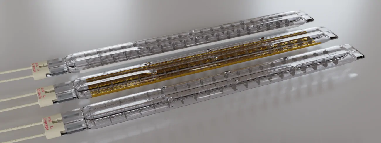
In an RTP tool, banks of lamps deliver radiation through an optical window to a single wafer. The tool raises the wafer temperature along a controlled trajectory, holds it when the recipe requires a dwell, and then manages cooling. Lamp power can respond rapidly, so the system can follow short thermal cycles and change recipes without heating a large furnace mass. Typical RTP-related operations may include annealing, oxidation, nitridation or other temperature-driven steps, but the acceptable ramp, peak temperature, dwell and atmosphere are process-specific.
The practical advantage is therefore controllability, not a universal efficiency percentage. Useful energy is the portion absorbed by the wafer and converted into the required temperature field. Energy that is reflected, transmitted, intercepted by the chamber or removed by cooling still affects the system balance. Lamp replacement or a new emitter array must be evaluated in the actual chamber rather than judged by electrical wattage alone.
A silicon wafer does not interact with lamp radiation as a fixed, ideal absorber. Its optical response depends on wavelength, temperature, doping, surface condition and the films already present. A deposited metal, oxide or other film can change both absorption of the heating radiation and emission measured by a pyrometer. The front and back surfaces may also behave differently.
Emitter selection should consider the lamp spectrum together with the quartz window, reflectors, shields, wafer support and chamber surfaces. A material that is transparent or weakly absorbing in part of the spectrum may send more lamp radiation into another component. A reflective film may reduce direct absorption while increasing multiple reflections inside the chamber. Those effects cannot be resolved from a catalogue wavelength label alone.
The heating model should include absorbed radiation, wafer emission, conductive exchange through supports and radiative exchange with surrounding surfaces. Cooling hardware changes the chamber boundary conditions and can influence edge loss or repeatability. Before production qualification, compare the model with instrumented-wafer or other validated temperature data over the intended recipe range.
Uniform incident irradiance does not automatically create a uniform wafer temperature. The edge often loses heat differently from the centre, supports can disturb the local field, and chamber geometry can redirect radiation. A useful lamp layout therefore combines optical design, independently controllable zones and feedback appropriate to the process.
A peer-reviewed RTP lamp-array design study modelled five concentric tungsten-halogen lamp zones for a 200 mm wafer. The work illustrates why lamp-ring radius, lamp population, array height and additional edge irradiance can be design variables. It is not a universal hardware recipe: real systems must also account for chamber reflection, convection or gas flow, process hardware and actual wafer properties.
| Design variable | Why it matters | What to verify |
|---|---|---|
| Lamp-zone geometry | Shapes the radial irradiance field | Centre-to-edge profile across the complete recipe |
| Zone power range | Provides correction authority during ramps and dwells | Stable control without saturation or excessive interaction |
| Window and reflector condition | Changes transmission and redirected radiation | Clean-state baseline and maintenance limits |
| Wafer support and edge hardware | Introduces local heat loss, shadowing or reflection | Repeatability at each support location and wafer size |
| Sensor location | Determines what temperature the controller actually observes | Correlation between indicated temperature and wafer temperature |
During commissioning, test more than one steady-state point. A layout that appears uniform at a hold temperature may behave differently during a fast ramp or cooling transition. Record spatial and temporal results together with zone commands so an apparent temperature problem can be separated from a control-limit or optical-distribution problem.
Non-contact temperature control is one of the most demanding parts of lamp-heated RTP. A pyrometer measures radiance in a defined spectral band and field of view; it does not directly read temperature without assumptions or calibration. Wafer emissivity can change with temperature and process history, while thin films can change it substantially.
In a NIST study of light-pipe radiometry in an RTP test bed, low-emissivity films produced indicated-temperature differences of up to 36 °C at 900 °C in the tested configuration. The number should not be transferred to another tool as a correction factor. Its importance is that film stack and emissivity must be part of calibration and uncertainty analysis.
Lamp and chamber radiation can also enter the detector path. Another NIST RTP calibration study found that heating-lamp light leakage could create significant low-temperature error in the tested light-pipe radiometer arrangement. Reflective cavities may improve effective emissivity in some geometries, yet gaps, apertures, windows and shields can alter the radiance reaching the sensor.
Define the measurement band and view path. Confirm what the sensor sees through the chamber hardware and whether direct or reflected lamp radiation can enter that path.
Characterise representative wafer stacks. A bare calibration wafer may not represent low-emissivity films or production surfaces.
Use traceable or validated references. Correlate pyrometer output with an instrumented wafer or another accepted reference method over the required range.
Validate transients as well as dwells. Sensor response time, lamp leakage and changing emissivity can affect ramp control.
Maintain the optical path. Window coating, deposits, reflector degradation and alignment changes can shift both heating and measurement.
The lamp is one element of the RTP tool. Quartz window transmission, reflector material, chamber cleanliness, process-gas compatibility and cooling capacity must be reviewed together. Deposits on an optical window can change the heating pattern. Particles from unsuitable mounts or insulation can conflict with cleanliness requirements. Gas chemistry and pressure can also affect which materials and electrical feedthroughs are acceptable.
Cooling is not only a lamp-life consideration. It stabilises seals, walls, reflectors, terminals and adjacent instrumentation, while defining the wafer’s radiative surroundings. Monitor the required water or air flow, inlet conditions and failure response. The equipment designer should establish interlocks for cooling loss, overtemperature, open access, process-gas faults, lamp or zone faults, control-signal failure and abnormal wafer handling. A safe state and restart sequence must be documented for the complete tool; they cannot be inferred from the lamp specification.
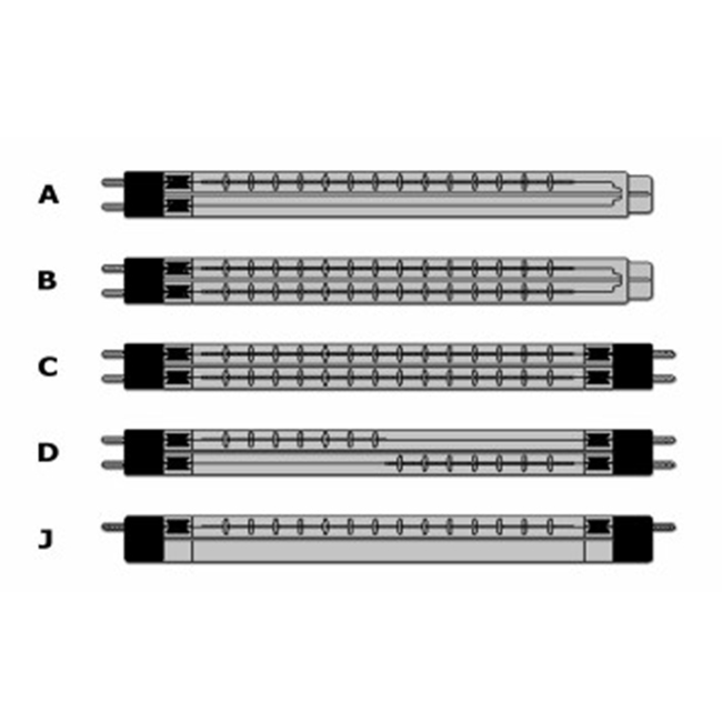
The images above show YFR lamp products, not a qualified semiconductor chamber or evidence of use at a wafer fabrication facility. Equipment suitability depends on the customer’s engineering review, material controls and process validation.
Define the thermal recipe. Record wafer diameter and stack, starting condition, ramp limits, target temperatures, dwell, cooling profile and allowable spatial variation.
Map the optical system. Document lamp positions, zones, window transmission, reflectors, shields, sensor ports, supports and the expected radiation paths.
Confirm component interfaces. Verify voltage, current, power-control method, lamp dimensions, end connections, mounting orientation, clearance and cooling.
Establish measurement traceability. Define calibration wafers, reference sensors, emissivity assumptions, uncertainty and acceptance criteria.
Test representative wafer stacks. Include surfaces or films expected to produce different absorption, reflection or emissivity.
Measure dynamic uniformity. Evaluate centre, edge and selected radial locations during ramps, dwells and cooling—not only at one endpoint.
Challenge disturbances. Check repeatability after maintenance, lamp replacement, window cleaning, recipe change and credible utility deviations.
Qualify safeguards. Test interlocks, alarms, safe shutdown, recovery logic and the effect of a failed lamp or control zone.
Freeze the approved configuration. Link lamp drawing, controller settings, calibration record, chamber condition and acceptance data under change control.
No. They are a heating source used in particular lamp-based thermal tools. Process chemistry, temperature range, atmosphere, cleanliness, optical access and control requirements determine whether this architecture is appropriate.
No. Wattage is an input specification. Wafer temperature depends on spectral absorption, geometry, distance, zone distribution, chamber reflection, heat loss, cooling and the control recipe.
The film can alter wafer emissivity and reflectivity in the sensor’s wavelength band. It may also change how lamp or chamber radiation reaches the detector. Representative-stack calibration is therefore important.
Not automatically. Multiple reflections can redistribute energy and change effective emissivity, but ports, gaps, shields and contamination may create non-uniform effects. Model and measure the real chamber.
Provide the lamp drawing or sample, voltage, wattage, overall and heated lengths, tube construction, reflector, end connections, operating orientation, cooling arrangement and tool interface. Process qualification still requires testing in the equipment.
YFR can review quartz infrared lamp dimensions, electrical ratings, reflector options and mechanical interfaces for component replacement or prototype radiant-heating assemblies. Browse short-wave infrared lamps and infrared heating systems and controls, or send the existing lamp drawing and equipment requirements for a compatibility review. Final chamber design, contamination control, equipment safety and semiconductor-process qualification remain the responsibility of the tool and process engineering teams.


