Author: Site Editor Publish Time: 2025-12-11 Origin: Site
Last updated: August 29, 2026
Infrared can preheat circuit boards, dry conformal coatings and support selected bonding or soldering stages. Electronics assemblies contain reflective metal, dark laminate and temperature-sensitive components, so a single lamp setting can create very different local temperatures. Process design must control ramp rate, shadowing and peak product temperature.
PCB preheating, coating drying and solder reflow have different chemical and thermal requirements. Confirm the material supplier's temperature window and whether infrared is the primary process, a preheat stage or a supplement to convection.
Black packages, laminate, solder mask and metal shields absorb or reflect radiation differently. Tall components create shadows. Use multiple zones, board motion or hybrid airflow where necessary, and measure representative hot and cold locations.
| Stage | Control objective | Evidence |
|---|---|---|
| Preheat | Controlled ramp and reduced thermal gradient | Board and component temperatures |
| Active heating | Reach coating or joining window | Time above required range |
| Hold or exhaust | Complete evaporation or reaction | Process-specific cure or dryness test |
| Cooling | Avoid handling damage and thermal shock | Exit temperature and quality |
Thermocouples attached to representative locations are useful for profiling. Non-contact sensors need suitable emissivity, field of view and protection from reflected lamp radiation. Do not control the process from air temperature alone.
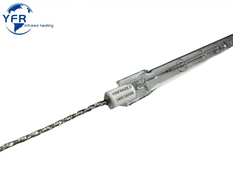
Fast-response lamps can overheat a stationary board quickly. Interlock heater power with conveyor motion and ventilation, and define safe restart behaviour. Review YFR short-wave lamps and power controls.
Only if the complete solder profile, atmosphere, uniformity and product requirements are validated.
Reflectivity and thermal mass can change absorption and response compared with dark components.
No. Measure critical components, joints or coating locations that define quality and damage limits.
Select through trials with the actual board, coating and required response rather than a universal rule.
Send YFR the board, process window and line layout for an emitter review.


